A big problem for users coming to Silhouette 3 from version 2.3 is the lack of some shortcuts that made the roto workflow in 2.3 so fast and comfortable.
The number one shortcut that is missing is the good old "Shift+A" to toggle between Alpha Overlay (with motion blur) and the Foreground.
The problem is the new "Node" architecture where you can only see motion blur when you're looking at the Output Node.
But the guys at SilhouetteFX listened and have added all the necessary keybinds so the old 2.3 workflow is now possible again (Well done guys!).
The ingredients are actually in the default keybinds.py but you still have to modify it a bit.
Below is an updated rgba() function. Just replace the old one with this one.
# RGBA mode
rgba_mode = False
rgba_prev_view = 0
rgba_prev_view_node = None
def rgba():
global rgba_prev_view_node
global rgba_mode
global rgba_prev_view
rgba_mode = not rgba_mode
if rgba_mode:
rgba_prev_view_node = fx.viewer.viewNode
rgba_prev_view = fx.viewer.viewMode
fx.viewer.setViewNode("OutputNode")
fx.viewer.setOverlay(False)
fx.viewer.setChannelMask(fx.Color(1, 1, 1, 1))
fx.viewer.setViewMode(0)
else:
fx.viewer.setOverlay(True)
fx.viewer.setChannelMask(fx.Color(1, 1, 1, 0))
fx.viewer.setViewNode(rgba_prev_view_node)
fx.viewer.setViewMode(rgba_prev_view)
fx.bind('Shift+a', rgba)
So with this function added you can now tweak your splines in the roto node while looking at the Roto Node Foreground View and by pressing "Shift+a" you can now jump to viewing the Output Node with Alpha Overlay and normal Overlay disabled. Pressing "Shift+a" again brings you back to the Roto Node Foreground View.
One very important shortcut that is still missing is a shortcut for looking at the Composite with motion blur. At the moment this is unfortunately not easily done.
SilhouetteFX would either have to add a keybind to enable/disable nodes (in this case the Composite Node / At the moment i don't know why there is a Composite Node anyway but maybe they want to add more sophisticated stuff to this node later) or add a Composite View to the Output Node (which would make a lot of sense imo).
Sunday, 3 May 2009
Friday, 10 April 2009
Customising shaders in Silhouette 3
What i love about Silhouette is that the developers let you customise a lot of stuff.
The ability to script your own keyboard shortcuts is invaluable for something as
keystroke intensive as paint & roto.
Another area that is customisable are the shaders. They control how the pixel values of your images are displayed on your monitor.
In Silhouette all the colour transformations defined in the shader happen inside the GPU of the graphics card in realtime.
That is why no new caching is needed when you change the viewer settings which is really helpful.
In Silhouette 3 these shaders are written in the OpenGL Shading Language (GLSL) which is similar to C and they can be found in the installation directory in the shaders folder.
I want to give you an example where such customisation might be useful.
One thing i was never really happy with in Silhouette are the limited ranges of the black and white point settings.
Per default the ranges are only 0 - 0.2 and 0.8 - 1.2 respectively and the values are used like the values in Shake's "Compress" node.
Well i prefer the "Expand" node usually and would like to extend the ranges of the sliders.
To achive this i changed the viewer_rgb.glsl shader (always a good idea to make a backup before changing the file) which is used for 8 and 16bit projects.
Below you can see the code i replaced the old black/white point code with:
// black/white point
float blackPoint2 = blackPoint*3.0-0.2;
float whitePoint2 = (whitePoint-1.0)*2.0+1.0;
float slope = (1.0/(whitePoint2 - blackPoint2));
c = slope * c - slope * blackPoint2;
First of all i remap the old black and white point slider ranges to -0.2 - 0.4 and 0.6 - 1.4 ( note that a interface blackpoint setting of 0.066 represents 0 in the shader now ).
Then i add the colour transformation function which in a lot of cases and also for an "Expand" is a simple linear function.
Quite easy and very helpful i think.
Tuesday, 11 March 2008
Better motion vector blur out of Nuke's Scanline renderer
Look at the following gif animation:
Do you think you can get that out of Nuke's scanline renderer without cranking up the multisamples but only with vector blurs?
It's not as easy as it seems.
To get accurate motion blur where an object changes direction, like you see in the example, you need forward and backward motion vectors.
The scanline renderer unfortunately outputs only one of them. You get forward motion vectors by setting the shutter offset to 0. You get backward motion vectors by setting the shutter offset to -shutter/2.
The effect of the shutter offset setting is very confusing when you output motion vectors.
From my technical understanding such a setting should actually only shift the point in time forwards and backwards from which the motion vectors are calculated.
The Scanline renderer definitely should have seperate controls to output both forward and backward motion vectors.
So how do you get both? Unfortunately at the moment it seems that you need two scanline render nodes and two vector blur nodes. Which means unfortunately doubling the render time. But that's still faster than cranking up those multisamples.
Take a look at the following setup:
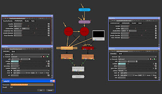
That's the setup i use to create vector motion blur from 3D.
You have two branches.
The one on the left is for backward motion blur. The one on the right is for forward motion blur.
At the end i mix both results with a dissolve which functions as a shutter offset.
The multiply setting in the vector blurs is linked via an expression to the dissolve settings.
One could also add another variable to the multiply settings expression to scale them. That variable would then function as a shutter angle setting.
Feel like creating your own vector motion blur gizmo or even creating your own scanline renderer gizmo now that incorporates all this stuff?
I was lazy till now. But will sure build my own soon. :)
Btw in Nuke 4.8 you could do the same with the motion vectors generated from 2d transformations by setting the shutter offset in the MotionBlur2D node to 0 and -shutter/4 (a bit confusing eh).
In Nuke 5 it seems to be crippled and can only output forward motion vectors (boo!).
Although for 2D transformations you have of course the nice timeblur where cranking the divisions up is not as time expensive as Multisamples in 3D.
As a whole i think the motion vector generation in Nuke 5 is inconsistent and confusing. I hope the Foundry changes that.
Enjoy!
And in the case that i'm overcomplicating things and this is all obsolete please let me know.
Saturday, 15 December 2007
Creating shortcuts in SilhouetteFX Roto/Paint for viewing RGB channels
One of the most highly missed keyboard shortcuts for Silhouette are shortcuts for viewing the RGB channels seperately.
In Silhouette all your keyboard shortcuts are defined in a python script called keybinds.py that can be found in the scripts folder in the install directory.
Editing a python script might scare off some users at first but editing the keybinds.py is surprisingly easy and fun and above all flexible
as it let's you add your own keyboard shortcut functions.
Even if you don't know Python you should be able to do basic customization of your shortcuts after a few minutes.
To create shortcuts for viewing the RGB channels you have to create your own little functions which you then assign certain keyboard shortcuts.
Here's the code i've added to the end of my keybinds.py:
# shortcuts for viewing colourchannels seperately
def viewR():
fx.viewer.setChannelMask(fx.Color(1, 0, 0, 0))
def viewG():
fx.viewer.setChannelMask(fx.Color(0, 1, 0, 0))
def viewB():
fx.viewer.setChannelMask(fx.Color(0, 0, 1, 0))
def viewRGB():
fx.viewer.setChannelMask(fx.Color(1, 1, 1, 0))
fx.bind('6', viewR)
fx.bind('7', viewG)
fx.bind('8', viewB)
fx.bind('9', viewRGB)
Quite simple and self explanatory.
By pressing 6,7,8,9 on my keyboard i can now switch between the colour channels and the full RGB view. Alternatively writing a "toggle" function to view the channels is also not that complex.
What use has that you ask? Well it's nice to view the channels seperately to decide which is best for tracking or to check if you might be able to
pull a key on one of the colour channels for some areas instead of doing roto.
Also for doing paint it's sometimes very important to check the colour channels seperately (e.g. when doing marker removals on bluescreens).
Have fun!
After figuring out how to create these functions i found out that John-Michael Bills had already written about these on the SilhouetteFX forums.
But i post it again here for all people that aren't registered at their forums.
Thursday, 28 June 2007
You like Shake's SmoothCam but SmoothCam doesn't like your 8bit images
A couple of months ago i came across a problem in Shake with the SmoothCam node, kinda solved it and forgot about it. Sometimes it's good to write down some bug workarounds down so you don't forget about them. So here is the problem:
I had to apply the SmoothCam node to some Roto mattes and i got a strange result. The SmoothCam node introduced artifacts in the RGBA channels.
Instead of being nice and having a value of 1.0 there were a lot of pixels that now had values of 0.996 forming patterns which changed for every frame.
Depending on the SmoothCam settings i got different results.
Here's one result when feeding a white (1.0) Color node into a SmoothCam node in 8bit:
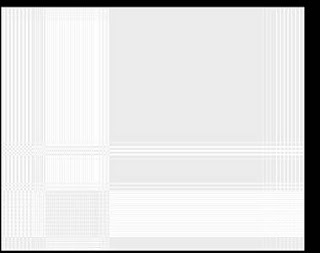
I've added an Expand with the Low Color set to 0.95 so the artifacts are easier to see. The first is the result with only translateLock activated the second with all locks switched on. Setting it to smooth produces similar results.
The hideous thing is that you might not easily see these artifacts on regular images and maybe have introduced these without even realizing it.
So what is the workaround?
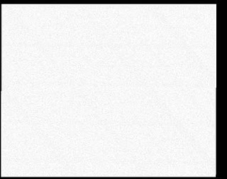
The good news is that these artifacts don't occur when working in 16bit or float.That means when working in 8bit you can just add a byte node set to 16bit before the SmoothCam and then add a byte node after that to bring it back to 8bit.
I've never read about this bug anywhere else and as we all know, it will probably never be fixed.
I had to apply the SmoothCam node to some Roto mattes and i got a strange result. The SmoothCam node introduced artifacts in the RGBA channels.
Instead of being nice and having a value of 1.0 there were a lot of pixels that now had values of 0.996 forming patterns which changed for every frame.
Depending on the SmoothCam settings i got different results.
Here's one result when feeding a white (1.0) Color node into a SmoothCam node in 8bit:

I've added an Expand with the Low Color set to 0.95 so the artifacts are easier to see. The first is the result with only translateLock activated the second with all locks switched on. Setting it to smooth produces similar results.
The hideous thing is that you might not easily see these artifacts on regular images and maybe have introduced these without even realizing it.
So what is the workaround?
The good news is that these artifacts don't occur when working in 16bit or float.That means when working in 8bit you can just add a byte node set to 16bit before the SmoothCam and then add a byte node after that to bring it back to 8bit.
I've never read about this bug anywhere else and as we all know, it will probably never be fixed.
Thursday, 22 March 2007
How to do a Divide operation in After Effects
From time to time people find that some essential stuff is missing in AE (ok to be honest something is always missing in any program).
With that i don't mean plug in stuff you can build yourself with some effects etc.
i mean basic operations that a compositor needs ( i'm not starting to rant here about the lack of 16bit and 32bit effects) .
Everyone building their own colour difference keys or despill functions are irritated by the lack of an Subtract transfer mode for example.
I know there are other ways to do this but you still lose time and make your comps more complex.
A more rare one is a Divide operation. Actually it's an essential operation for working with images with premultiplied alpha channels, where one very often needs to divide the image by it's alpha channel to revert the premultiplication.
But as AE handles that in most cases in the Interpret Footage dialog and hides most of the whole concept from the user, not everybody knows of it's importance.
Ok, besides that, there are probably not that many situations where you might need it, but when you do, you're in trouble.
An example would be an Ultimatte style screen correction.
While fiddling with AE and "The Partially Transparent Alpha Pixel Problem", as described in Steve Wright's book "Digital Compositing for Film and Video", i found a workaround for Divide in AE.
AE has an un- premultiply operation outside of the the Interpret Footage dialog, one can use that for for ones Divide needs.
It's a bit far out, but it works.
Ok, here we go....
You have two grayscale layers A and B which you want to divide: A/B
Put both in a comp.
Add a "Channel-> SetMatte" Effect to A.
For "Take Matte From Layer" choose - B.
For "Use For Matte" choose - Red Channel,Green Channel or Blue Channel.
Uncheck all the other items
Add a "Channel-> Channel Combiner" to A.
Choose "From" - Straight to Premultiplied.
check "Invert"
Add another "Channel-> SetMatte" to A.
For "Use For Matte" choose - Full
Uncheck everything.
You just divided image A by the red, blue or green channel of image B.
Ok, why does this work?
Well first you set one of the color channels of image B as the alpha of
image A.
Then you added an effect where you can multiply a image with it's alpha channel (an alpha premultiply).
By checking "Invert" we use an alpha unpremultiply instead.
That means we divide the image (layer A) by its alpha channel (a channel of layer B).
In the last step we clear layer A of its temporary alpha channel by setting alpha to full (white, 1).
I'm sure you know how to make this work with non grayscale images if needed.
As a side note: "Channel Combiner" is only an 8bit effect.
Friday, 16 February 2007
3D camera tracking data import into After Effects troubleshooting
Almost everyone trying to import 3D camera data created in matchmove programs into AE has run into some problems from time to time. I hope this article can be helpful to solve some of these problems.
In this troubleshooting article i'm not gonna write about import from Maya. Primarily because i don't own the software and also since it seems that with the right settings in Maya the import into AE is very reliable.
That reliability was and is unfortunately not always given with the export from a matchmove program (because of AE or the matchmove program?).
The usual import route to AE is via the Maya ma format. The only exception i know of is the import from Boujou via the Boujou ban format with a free AE plug in from 2d3 (for me this worked pretty well sometimes and sometimes it didn't work at all).
The import via the ma file format can create a lot of problems. It seems that Maya can read the exported files from matchmove programs well but AE is a little bit more demanding. This results in the usual 320x240 comps with missing tracking marker nulls etc.. Very annoying to say the least.
The workaround for this for many people was to import the file into Maya and then export a Maya file that AE can import properly.
Now with newer versions of Boujou and also SynthEyes there's an export option called AE Maya format that puts out a ma file that AE can read well (if you know other 3d tracking software with this feature let me know).
Although i always wanted to know why the standard ma import didn't work well with AE, the availability of the new AE Maya format export options made me forget about this problem.
A recent discussion at fxphd reawakened my interest in that topic.
As a result i checked the differences between the AE Maya and standard Maya format to find out what causes the indigestion in AE and how to change the standard maya file to make it work.
So this is designed as a help if you only have matchmoving software that doesn't feature an AE Maya export option ( like Realviz's Matchmover ) or if you're just stranded with a standard maya file.
For my testing i only had 2d3's Boujou Bullet PXC and Realviz's Matchmover 4 Pro available ( thanks to the Pixelcorps ).
The example code below is from an standard maya file exported from Matchmover Pro 4 but the solutions are easily applicable to files exported from other matchmove programs.
Overall tips:
- don't export 2000 tracks etc.. only export a couple hundred or the ones
you need. Otherwise AE won't be able to handle it.
- try to use the scaling with a coordinate system in the matchmove program to get a proper scene scale.
- try to set the coordinate axis in your tracking program to y-up and also set up a coordinate system for your solve.
Still if the tracks and camera aren't positioned and oriented properly after import you can always parent all tracks and the camera to a null and rotate and move this around.
How to make a standard Maya ma file work with AE:
1. Backup your ma file (at a safe place!) and then open it in a standard text editor ( i know you don't want to do this
but hey it's easy... trust me :) ).
In case the file isn't formatted properly use a different editor.
2. Go to this line:
// edit this line to change the current units
currentUnit -l cm -a deg -t film;
Check if the word after -t is set to film for 24fps, to ntsc for 30fps or to pal for 25fps;
This should usually be set to the framerate that was used in the matchmoving program.
In one test with Matchmover it was set to film instead of ntsc.
3. Go to this line:
// the five next lines set global render attributs
// comment or edit these lines as necessary
select -ne defaultResolution;
setAttr ".w" 720;
setAttr ".h" 480;
setAttr ".dar" 1.34997;
setAttr ".ldar" yes;
Add a colon before “defaultResolution” so you get this ( if you use Matchmover also correct the typo in attributs ;) ):
// the five next lines set global render attributes
// comment or edit these lines as necessary
select -ne :defaultResolution;
setAttr ".w" 720;
setAttr ".h" 480;
setAttr ".dar" 1.34997;
setAttr ".ldar" yes;
Now this little colon solved the 320*240 comp issue. If you save now and import to AE your comp should be the correct size and framerate and you should have a correct camera motion (only the tracking points are still missing).
What would interest me is if the Maya ma format specification actually requires this colon and Maya is just more forgiving on import or if the AE import is too unforgiving?
Ok let's continue with making the tracking points show up in AE.
4. Check out this line which stands for one track (different programs put out different naming and parenting, also in this example it is an Auto track while there could also be differently named tracks like locators, manual tracks etc.) :
createNode transform -n "Auto0000" -p "Auto_Tracks";
setAttr ".t" -type "double3" 7.86996 4.28757 -15.3173;
setAttr ".s" -type "double3" 1 1 1;
createNode locator -n "Auto0000Shape" -p "Auto0000";
setAttr -k off ".v";
To make it work properly it should look like this:
createNode transform -n "Auto0000";
setAttr ".t" -type "double3" 7.86996 4.28757 -15.3173;
setAttr ".s" -type "double3" 1 1 1;
createNode locator -n "null_Auto0000Shape" -p "Auto0000";
setAttr -k off ".v";
AE won't create a null for your tracking point if the locator name doesn't start with “null_”.
If you leave the “-p "Auto_Tracks" “ in there (which is a command for parenting) AE will create 2 nulls or more with loads of parenting for every single Track which is unnecessary.
Test it out yourself and get rid of it.
The first attribute is the position of the null and the second the scaling. Scaling will determine the scaling percentage of the nulls created in AE during import. Every track you exported from your matchmoving program will result in the creation of a null with a size of 100x100 pixels.
Scaling set to 1 ( 1% ) will result in a reasonable null size in your comp (although this depends a lot on your scene scale, in a large helicopter shot this could need to be set higher). You can of course also change this in AE after import. In the Matchmover Pro export dialog, point scale will set this value. In Boujou i think it defaults to 5.
Changing those names etc. is best done with the replace function in your favorite editor where you should have an interface similar to this:
Replace: createNode locator -n "
by: createNode locator -n "null_
and
Replace: -p "Auto_Tracks"
by:
Clicking "replace all" will make the computer do all the work on the hundreds of tracks.
5. Save the file. Import into AE and be happy! :) In case something doesn't work, play around with the file some more or write me a comment that my instructions are crap ;).
Disclaimer: I'm not responsible for messed up maya files. Make a copy of the file to a safe place before playing with it.
Subscribe to:
Posts (Atom)